Lumopt
Choosing an MPO optical transceiver is not just a matter of matching port speed. The connector, fiber type, reach, polarity, and link budget must work together. A mismatch can leave a link dark, even when the transceiver fits the cage. Small details matter.
For an honest expert perspective, this introduction uses a clearly fictional composite specialist, optical engineer Mara Chen. Her editorially created reminder is: “Match the optics to the complete link, not just the port.” Treat that line as a practical principle, not a quotation from a real interview. The guide that follows examines the checks behind it, from single-mode or multimode fiber to lane count, wavelength, and transmission distance.
Look closely at the installed path. Is it a short connection between switches, or a longer run through a patch panel? Check the MPO connector configuration, including pinning and polarity, against the cabling plan. Confirm the transceiver’s speed and breakout mode match the switch and the far-end device. Then review optical loss limits and vendor compatibility. A datasheet helps, but it cannot reveal a dirty end face or an undocumented cable change. That is where careful inspection—and, when needed, testing—matters. No checklist removes every uncertainty. Still, a methodical review can prevent costly mismatches and make the final choice much clearer.
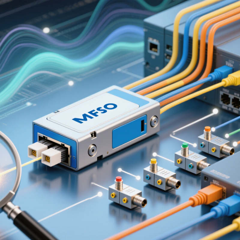
An MPO optical transceiver converts electrical signals from a host device into optical signals, and converts incoming light back into electrical signals. Its front port accepts a multi-fiber MPO connector instead of a single duplex pair. Inside, transmitter and receiver components align with multiple fiber cores in a shared ferrule. Small geometry matters. Guide pins, connector orientation, and clean end faces help maintain lane alignment and limit optical loss.
Parallel links use separate fiber groups for transmitting and receiving, but fiber counts vary by transceiver design. An eight-lane interface carries several data streams at once; a 12- or 16-fiber connector may provide additional positions for those lanes. The module also handles functions such as optical modulation, signal conversion, and diagnostics. Heat and power matter, too. A dense port can simplify cabling, yet make airflow and access harder.
The Ethernet Alliance’s 2024 Ethernet Roadmap identifies 800GbE and 1.6TbE speeds, highlighting why lane count and connector compatibility deserve careful attention. When assessing a module, compare its optical interface, fiber arrangement, and polarity with the link design. A matching connector alone is not enough. Small polarity or fiber-count mismatches can leave a link dark, and labels do not always make the mapping obvious. It is worth checking the actual port diagram.

How to Choose the Right MPO Optical Transceiver?
Key Specifications to Compare Before Choosing an MPO Transceiver
Start with the link speed, fiber type, and required reach. An MPO connector does not guarantee compatibility. Check whether the module uses single-mode or multimode fiber, its wavelength, and its supported distance. Then compare fiber count and lane mapping: an 8-fiber link and a 12-fiber link may look similar at a glance, but their connections can differ. Verify connector polarity and key orientation against the cabling plan. The Ethernet Alliance’s 2024 Ethernet Roadmap tracks the industry’s move toward 800 Gigabit Ethernet and 1.6 Terabit Ethernet. That roadmap is a useful reminder: higher capacity makes lane and fiber planning more important.
Compare optical transmit and receive limits, insertion loss, and receiver sensitivity with the link budget. Include patch panels and mated connectors; each adds loss. Check power consumption, operating temperature, and digital diagnostics if the module will run in a dense switch. IEEE Ethernet specifications define interface requirements, while IEC 61754-7 covers MPO connector interfaces. Neither replaces checking the specific module’s compatibility with your equipment. I still recheck polarity before deployment. A small mismatch can leave a carefully planned link dark.
Tips: Label both ends before connecting. Inspect and clean end faces, then test insertion loss with suitable equipment. Keep a little margin in the loss budget; real installations rarely match the neat spreadsheet.
How to Choose the Right MPO Optical Transceiver?
Matching an MPO transceiver starts with the fiber already installed. Check whether the link uses multimode OM3 or OM4, or single-mode OS2, then confirm the connector’s fiber count and polarity. An MPO-12 interface may carry eight active fibers for 40G or 100G parallel optics, while other applications use different fiber arrangements. Details matter. IEEE 802.3 reach specifications, for example, list 100GBASE-SR4 distances of up to 70 meters on OM3 and 100 meters on OM4. Treat those figures as limits, not design targets; patch panels and dirty connectors can reduce margin.
Next, verify that the transceiver matches the equipment’s port speed, lane configuration, and supported optical standard. A transceiver that physically fits may still fail to link. Check the switch documentation for supported modules, FEC requirements, and breakout modes, such as one high-speed port splitting into several lower-speed links. The Ethernet Alliance’s Ethernet Roadmap tracks transitions toward higher interface speeds, reinforcing the need to plan for equipment generations—not just today’s port. Still, roadmap trends do not guarantee compatibility with a specific switch. Record the installed fiber type and link length, then test the complete path. A detail teams sometimes overlook: MPO polarity can reverse transmit and receive paths. It is worth rechecking.
| Network Application | Typical Transceiver Type | Fiber Type | MPO Fiber Count |
|---|